Hardware Development
Custom Electronics Design and Manufacture
Do you need a custom control PCB for your new product? Blue Sparq has made the process easy, just give us a call (239) 558-8810 and our experienced embedded hardware engineers will listen to your requirements and put together a plan and proposal for you! We will pull from thousands of existing, tested and proven circuits and schematics to build your custom control electronics. All of our circuit board designs are made using our own vetted component library. Every component in this library has been verified for footprint fit and function. Using this special component library and existing successfull designs as the foundation of your new PCB helps accelerate the design and development process while increasing confidence that the first PCB will work perfectly. Small, single PCB or complex Multi-PCB designs all fit in our wheelhouse. Many years ago, Blue Sparq added a complete high speed SMT electronics assembly and production line to help its customers produce small quantity prototypes and production runs. We are able to keep our development fees low by manufacturing everything we design. We can also provide all of the design files for you to produce the PCBs on your own, however this requirement will be reflected in the development proposal.
IoT Hardware Design
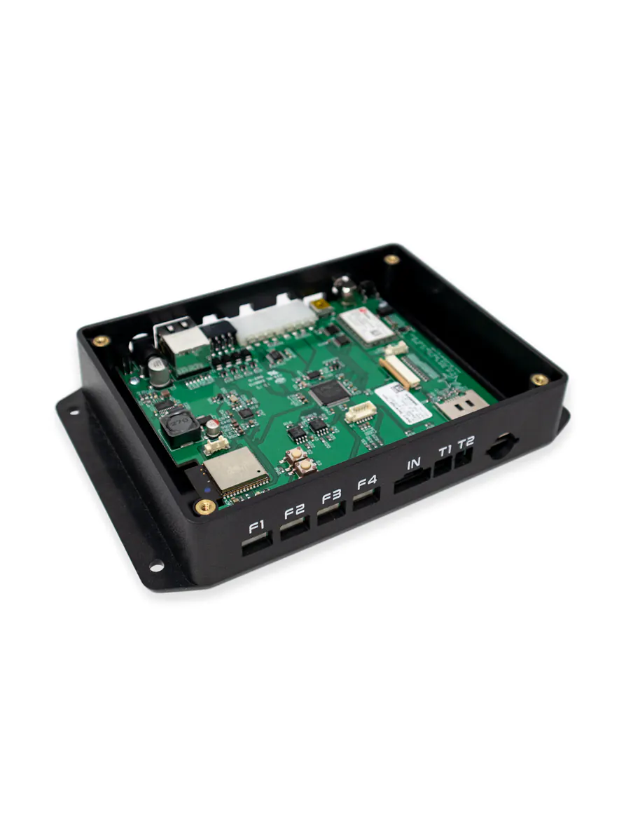
IoT is our specialty. Most of our customers want their machines or devices connected to the Internet. Our comprehensive IoT designs can be connected to the internet via Cellular CAT1 / CATM1, Ethernet or WIFI. This type of IoT design can be made using a simple micro-controller running line by line code, or using a much more powerful processor capable of running Linux. We can help decide which form of architecture to use based on your functional requirements.

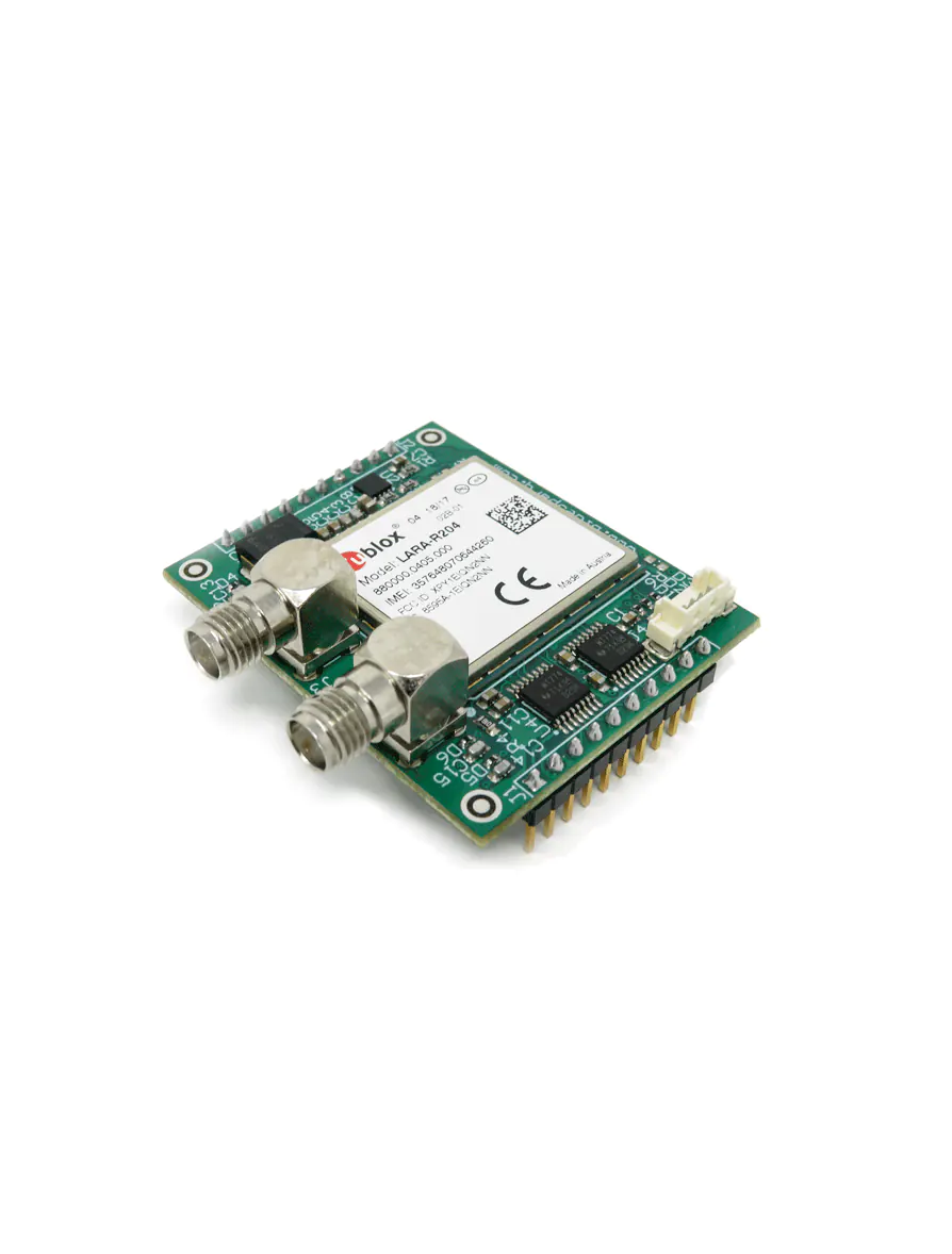
The most popular method of connecting hardware to the cloud is with an embedded cellular modem. We have designed, manufactured and certified CATM1 and CAT1 Plug and Play Modems as well as complete end devices. Most of these devices can be seen on the Verizon Open Development Website. Without the expensive and time-consuming network certification, Verizon will not allow your new device to be active on their network. Making and certifying Plug and Play versions of our modems has given our customers a huge advantage in time to market and reduced development cost. We simply add our Plug and Play cellular modem socket to your new PCB. By using our existing certified cellular modem end device, you will not need to get your product certified.
Blue Sparq has direct relationships with Verizon, KORE, and Hologram allowing for the best data plan pricing available. This coupled with our simple new customer onboarding portal, makes activating new SIM cards a breeze. Finally, our activation portal doubles as an automated billing system, making sure all of your customers are charged their monthly fees. This new customer onboarding and data plan / IoT Monitoring billing platform can be White Labeled to provide your customers consistency in branding.
Bringing WIFI and Ethernet to our designs was made easy by Espressif's ESP32 Modules. Their powerful Wi-Fi + Bluetooth modules are perfect for a wide variety of IoT applications. For Ethernet, a PHY is connected to the ESP32 through its reduced media-independent interface (RMII). Some customers want all three types of internet connectivity for their new IoT products. They want to give their customers a flexible way to connect to the internet. When installing the device, if an Ethernet connection is unavailable, then they would choose Wi-Fi. If Wi-Fi becomes unstable, then you can rely on a rock solid Cellular connection.
Carrier Board Design with LCD Touch Screen integration
Raspberry Pi Compute Module
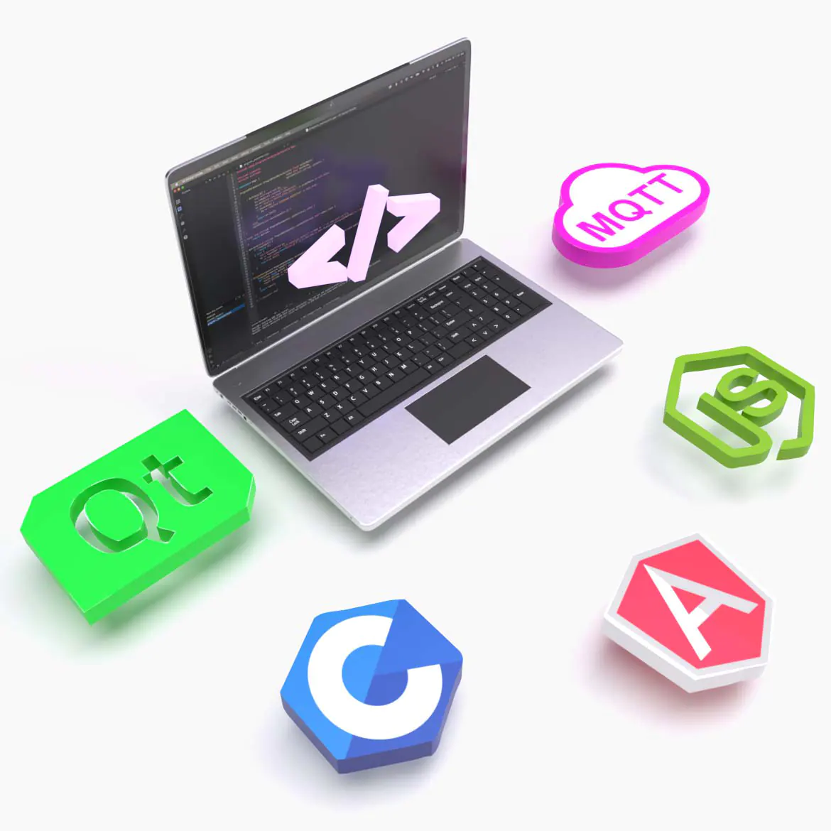
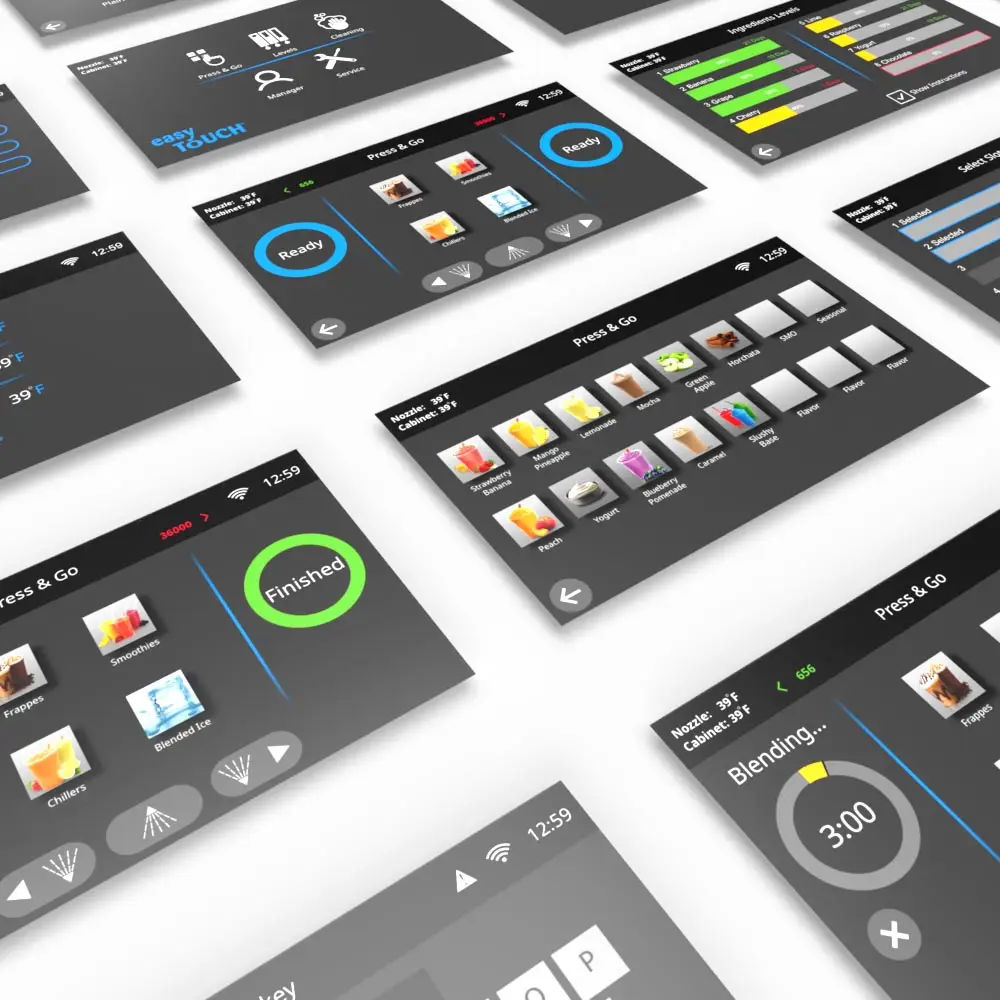
We have developed several custom carrier boards for the wildly successful Raspberry Pi CM3+ Compute Module. Our carrier boards have wide input range power supplies as well as the standard USB and Ethernet connectivity, RS-232 or RS-485 and a battery backed up RTC. The addition of our Plug and Play Cellular socket allows us to use any one of our existing certified CATM1 or CAT1 cellular modems. Finally, the LVDS circuit allows for easy integration of our 7" or 10.1" LCD capacitive touch screen displays. Our standard display cover glass is available with or without black border and is 3mm thick. These were made specifically for commercial kitchen appliance and unattended vending / kiosk applications. We can design a carrier board for your specific application. We have developed a Yocto Linux image that includes Mender.io's delta update functionality. This Linux image is the foundation of all of our QT based User Interface designs.
STM32MP1
A carrier board design requires a carrier PCB and a SOM, System On Module. This is a 2 piece system, where we normally design and manufacture the carrier board and purchase the SOM from the SOM manufacturer. In this type of system, you will be paying for 2 assemblies and 2 profit margins. A truly low cost design would require a single PCB design. This means having the complex SOM design integrated into the final PCB. We have done this with our STM32MP1 Miniature Display Computer board. Our first board has MIPI and RGB display capability.
USB
USB or Universal Serial Bus is a common interface that enables communication between devices and a host controller such as a personal computer. The most common USB connectors are displayed below.


When it was first released by Intel in 1996, the idea was right there in the name: Universal Serial Bus. To be universal meant that it had to just work. USB was designed to replace serial ports, parallel ports, mouse and keyboard ports which all required a fair amount of software support. With USB, simply plug in your device and it works.
The most common USB device we make is our custom capacitive touch USB keypads, mouse touch pads and joysticks. We can map the buttons to any key on a computer keyboard, mouse or joystick. Since we use the USB HID protocol, our keypads do not require any special software. Simply plug it in and it will just work.
The next most common USB device we make is our custom control boards using USB CDC. USB CDC is a composite Universal Bus device class or communications device class. This class can be used in embedded systems found in industrial equipment such as CNC machinery, industrial controls equipment and robotics. USB CDC makes the connection between USB and RS-232. The USB host makes the USB device appear as a traditional RS-232 device. We can use Modbus over USB and do file transfer.
The USB connection can be used to update the device firmware using a boot loader. The USB connection allows us to use a PC to configure the device. Doing this allows us to keep the user interface of the device simple, without sacrificing the ability to completely configure the device using the rich user interface of the PC.
There are two main ways that we implement USB communication in our custom electronic control designs.
- We choose micro controllers or processors that have USB peripherals. We design our hardware and write our firmware to make use of these USB peripherals.
- If our micro controller or processor does not have a USB peripheral, we use an IC like the MCP2200 or the MCP2221A. These ICs convert USB to UART or I2C.
If multiple USB host ports are required, we have used 2, and 4 port USB hub ICs. For example, the Microchip USB2412 is a simple 2 port USB hub. The Microchip USB2514B/M2 is a good 4 port hub. The Microchip LAN9514 IC has a 4 port USB hub and adds 10/100 Ethernet.
UART, RS-232 and RS-485
UART stands for Universal Asynchronous Receiver / Transmitter. The UART is used for serial communication with a device. You will find the UART peripheral in many micro controllers and processors.
The UART peripheral of a micro controller will communicate using a TTL level signal. If your micro controller is operating on a 5V supply, then your TTL levels will be 0 bit = 0V and 1 bit = 5V. If your micro controller is operating on a 3.3V supply, then your TTL levels will be 0 bit = 0V and 1 bit = 3.3V. The UART will transfer one bit at a time at a specified rate. This rate is called the Baud Rate.
It is important that this TTL signal is only used for short distances. Since TTL levels are only 3.3V or 5V, they are susceptible to noise, interference and degradation. If long distances, usually off board communication is required, the TTL signal will be converted to RS-232 or RS-485.
At one time, RS-232 was the most widely used communication standard on the planet. RS stands for “Recommended Standard.” Just like the UART, RS-232 is single ended, which means that a single electrical signal is compared to ground to determine the binary logic state (0 or 1).
An RS-232 signal will have a signal swing that is usually between -13V to +13V. This higher voltage makes the signal less susceptible to noise, interference and degradation thus allowing the signal to travel longer distances.
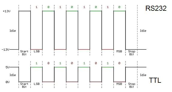
The RS-232 standard conservatively specifies the length to 15 meters or 50 feet. The baud rate and capacitance of the cable will affect this length. If 9600 Baud is used over CAT 5 cable, this maximum length increases to approximately 150 meters or 500 feet.
The RS-232 standard defined a 9-pin connector called the DB9. The pin out for the male DB9 connector is shown below:

You will not find these connectors on the back of computers or laptops anymore. Now USB to RS232 adapters are used to achieve the same thing. Here is an example of one that we use often:
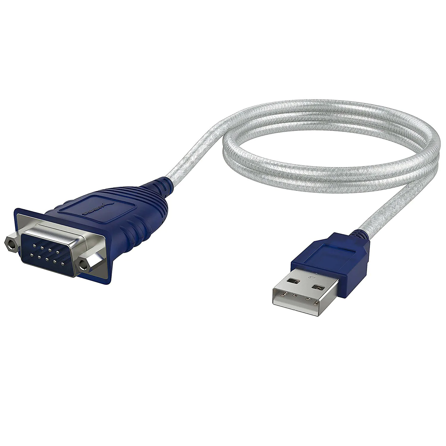
It is very common to convert from UART to RS-232 when the signal must leave the circuit. To do this, we use an ST3232 or MAX232 Transceiver IC.
What is the difference between RS-232 and RS-485?
- RS-485 uses differential signaling while RS-232 is single-ended.
- RS-485 is not only a single device-to-device interface, it also can be used to create networks of multiple devices.
- RS-485 can also operate at higher baud rates and has better noise immunity.
Below is a comparison between TTL UART signal vs RS-232 vs RS-485

It is very common to convert from UART to RS-485 when you want to have a multi-drop or daisy chain network. This means you can have one master device and many slaves. We use this a lot when we need to have distributed control over a machine. To do this, we use an ST485EB Transceiver IC and use dip switches on the slave PCBs to easily set their address
This is an example of an RS-485 multi-drop or daisy chain network topology:

We generally communicate with the MODBUS protocol over RS-485 when we use RS-485.
Ethernet
Ethernet is the most common technology used for connecting wired Local Area Networks (LANs). Ethernet enables devices to communicate with each other using a data-link protocol in the TCP/IP stack. Ethernet describes how network devices should format and transmit data so other devices on the same network can recognize, receive and process them.
Most people know Ethernet is how their computer connects to the Internet. Ethernet is the most robust way to connect to the internet because it is a wired connection. Wired connections are less susceptible to noise and interference. Ethernet is our first choice when connecting a device to the internet. If Ethernet is not available, we can choose WIFI or Cellular to connect to the internet.
We have worked with several customers that require an Ethernet connection between their control panel and the rest of their system. One example of this is the FOY control panel.
We mainly use Ethernet to connect our IoT devices to the internet. We prefer Ethernet because it generally just works! The problem that we run into is Ethernet is not available in the desired location of the device.
For our complete IoT telemetry devices, our customers want WIFI, Bluetooth and Ethernet. In this case, we may use the Espressif ESP32-WROOM-32 module. Espressif supports SSL/TSL and MQTT without requiring any additional licensing fees making it a very low-cost solution to a very complex requirement. The Espressif ESP32 module has ethernet support making it the perfect choice for IoT applications.
When designing our custom Raspberry PI compute module carrier boards or ST / NXP SOM carrier boards, we generally use the LAN9514 IC because we can have 4 USB host connectors and a 10/100 Ethernet port.
If the customer requires us to make a capacitive touch keypad that communicates button presses via Ethernet, we may use the Atmel ARM ATSAME53J18A which is a 32-bit ARM Cortex-M4F CPU running at 120 MHz. This processor features a 10/100 Ethernet MAC with IEEE 1588 support. We prefer this IC because it reduces the foot print required for the PCB, allowing us to focus on capacitive touch button performance and optimizing the uniformity of our LED button lighting.
MODBUS
Modbus is a communication protocol used for transmitting information over serial lines between electronic devices. In a standard Modbus network, there is one Master and several Slaves. Each Slave will have a unique Slave address. The official Modbus specification can be found here: http://www.modbus.org/
Modbus is an open protocol, which means that it is free for custom hardware designers to build into their products and equipment without having to pay royalties. It is a very common protocol used widely through many industries.
We have designed custom products using the following:
- Modbus over USB
- Modbus over RS-485
- Modbus over Ethernet
We have even done file transfer using the Modbus protocol. This was required in order to do firmware updates on slave devices.
I2C
I2C was designed to allow easy serial communication between components on the same circuit board. The name I2C means “Inter IC.” Sometimes this bus is called IIC or I²C.
I2C has the following features:
- Only two bus lines are required
- SDA = Serial Data
- SCL = Serial Clock
- No strict baud rate requirements like RS-232 because the master generates the bus clock
- Master / Slave system
- I2C is a true multi-master bus providing arbitration and collision detection
There are several reasons why we use I2C. First off, it only requires 2 wires (SDA and SCL). These 2 wires can support over 1000 slave devices. Because I2C is a multi-master system, it can allow more than one master to communicate with all the devices on the bus.
We generally use I2C to communicate between ICs that have I2C interfaces and our micro controllers or processors. A good example of this is our RTC or real time clock / calendar IC. We have used the NXP PCF8523T/1,118 IC when our processor does not have its own built in RTC. This IC keeps accurate time so that we can do things like send time stamps with our sensor data. This part only communicates via I2C so we must use I2C to interface it with our micro controller or processor. The Raspberry Pi Compute Module CM3+/32GB that we use as a display computer does not have an RTC. The carrier boards that we make for this compute module almost always have an RTC with a battery backup. This way if the power is turned off, the battery keeps the clock alive. The next time this device is turned on, it should still have the correct time and date.
Sometimes our customers will ask us to make custom hardware that will communicate with their product’s main processor using I2C. Since we have done this several times, we have come up with an easy to use I2C protocol document describing how this communication should take place. This gives our customer’s engineers the ability to quickly write the necessary firmware required to interface with the new hardware that we have designed for them.
SPI
SPI stands for Serial Peripheral Interface. This interface bus is commonly used to send data between micro controllers and peripheral ICs such as SD cards and sensors. SPI has four connections. MOSI, MISO, Clock and Chip Select.
- MOSI stands for Master Out Slave In
- MISO stands for Master In Slave Out
- The Clock line synchronizes the Master and the Slave.
- The Chip Select line allows the Master to activate the chip that it wants to communicate with.
We generally use SPI to communicate between ICs that have SPI interfaces and our micro controllers or processors. A good example of this is the SD Card. We have added SD Cards to several of our embedded designs that use a SOM or System on Module. The Raspberry Pi Compute Module CM3 that we use as a display computer does not come with an SD Card connector. The custom carrier boards that we make for this SOM can use an SD Card to store the operating system and application software. When the computer is powered on, the processor can boot from this SD card or from the program memory built onto the compute module.
Sometimes our customers will ask us to make custom hardware that will communicate with their product’s main processor using SPI. Since we have done this several times, we have come up with an easy to use SPI protocol document describing how this communication should take place. This gives our customer’s engineers the ability to quickly write the necessary firmware required to interface with the new hardware that we have designed for them.
CAN
CAN stands for Controller Area Network. CAN is a robust vehicle bus standard which enables communication between microcontrollers and devices in applications that do not have host computers. It uses a message-based protocol.
CAN is being widely used in passenger cars, buses, and factory automation. CAN bus data transfer speeds are very fast because multiple messages can be sent simultaneously to all connected devices, sensors and actuators. CAN bus is a two-wire system which requires much less wire making them easier to install. This reduces complexity, cost and weight. It is very easy to diagnose problems with CAN bus because it is not sensitive to magnetic interference.
We have developed several control systems that use CAN bus. We use Microchip microcontrollers that have CAN bus peripherals built in. One example of this is the PIC32MX795F512 microcontroller, which has a CAN 2.0B module.

LVDS
LVDS stands for Low-voltage differential signaling. LVDS is a high-speed digital interface used in many applications that demand low power consumption and high noise immunity for high data rates.
Our 10.1” and 7” LCD panels have the LVDS interface. We have connected these LVDS Displays to the Raspberry Pi single board computer through the Texas Instruments SN75LVDS83ADGGR Flatlink Transmitter IC. We have developed several custom carrier boards for the Raspberry PI CM3 compute module which have this LVDS display capability.
MDB and DEX
MDB stands for Multi Drop Bus. It was created to standardize the way the VMC (Vending Machine Controller) would detect and communicate with various peripherals such as the credit card reader, bill validator, and coin mechanism.
We have developed vending machine telemetry devices that communicate sales information up to the cloud using Cellular, Wifi, and Bluetooth connectivity. We have even built our own cashless payment devices that connect to the vending machine via MDB.
We have designed a USB to MDB converter pcb that allows us to add vending machine payment hardware to any computer. Now you can add a cashless payment credit card reader, bill validator, or coin mechanism to a kiosk or drink dispenser.
DEX is a technology that provides transfer of important vending machine information such as money in the cash box, bill validator and coin mechanism, total sales, individual selection sales and other vending machine activity.
DEX is found in most vending machines. We will connect our device to the DEX port to transfer information to and from the vending machine.
Motor Driver / Controller
Our DC Brushed Motor and Stepper Motor control circuits have been in use for over 20 years and can be found in thousands of industrial devices. Based on your requirements, we will choose the most appropriate motor control design for your application. We can also help you specify the correct motor and gear box / power transmission for your application. The following is a brief description of how we control DC Brushed Motors, Stepper Motors, Brushless Motors and Universal AC Motors.
DC Brushed Motor
A brushed dc motor consists of an armature or rotor, a commutator, brushes and a field magnet. When DC power is applied to the brushes, they charge the commutator inversely in polarity to the permanent magnet, in turn causing the armature to rotate. The rotation direction can be reversed by reversing the polarity of the voltage applied to the brushes.
If a motor control system requires bi-directional control over the Brushed DC Motor, we use an H-bridge. An H-bridge is made up of four switching elements, with the Brushed DC Motor at the center, in an H-like configuration:
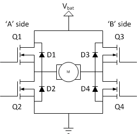
The switching elements (Q1..Q4) are usually bi-polar or FET transistors, and in some high-voltage applications, IGBTs. The top-end of the bridge is connected to a power supply and the bottom-end is grounded. The basic operation of an H-bridge is fairly simple: if Q1 and Q4 are turned on, the left lead of the motor will be connected to the power supply, while the right lead is connected to ground. Current starts flowing through the motor which energizes the motor in the forward direction and the motor shaft starts spinning.

If Q2 and Q3 are turned on, the motor gets energized in the reverse direction, and the shaft will start spinning backwards.
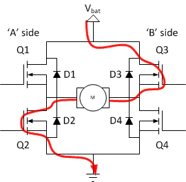
Q1 and Q2 should never be turned on together. This would create a shoot through condition, which means you are connecting your power supply to ground.
Stepper Motor
Stepper Motors are DC motors that move in discrete steps. They have multiple coils that are organized in groups called phases. By energizing each phase in sequence, the motor will rotate one step at a time. We have designed several beverage dispensing systems using the ST powerSTEP01. The powerSTEP01 is a system-in-package integrating 8 N-channel 16mΩ MOSFETs for stepper applications up to 85V. It has an SPI programmable controller, providing full digital control of the motion through a speed profile generation and positioning calculations.
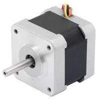
The TMC2208, TMC2209, A4988, and DRV8825 are great for smaller stepper motors that do not require a lot of power.
Brushless Motor
A Brushless DC Motor is essentially a Brushed DC motor turned inside out. The brushes and commutator have been eliminated and the windings are directly connected to the control electronics. The control electronics replace the function of the commutator and energize the proper winding at the correct time. Windings are energized in a pattern which rotates around the stator. The energized stator winding leads the rotor magnet and switches just as the rotor aligns with the stator.

The MTD6501 single chip driver or MCP8024 MOSFET Gate driver are good choices for controlling brushless motors.
Universal AC Motor
A universal AC motor is a special type of motor which is designed to run on either DC or single-phase AC supply. These motors have armature and field windings that are in series which produce high starting torque. We have used this type of motor for ice-beverage blending applications.
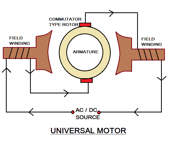
In our blender application, it is important that we have a lot of torque at low rpm. In order to achieve this, we control the motor using a DC supply and use a tachometer as feedback. If our goal is to run the motor at 100rpm our control system will PWM the motor and look at the tachometer feedback. If there is a load applied that reduces the rpm, we increase the PWM duty cycle to maintain the intended speed. This DC PWM Chopper method of controlling a Universal Motor can achieve better current control, better EMI behavior and ultimately be more efficient.
Lithium Battery Powered Devices
All of our wireless, hand held devices are powered by rechargeable batteries. When it is time to recharge, we just plug them in. We can design your product to operate and function the same as these standard devices. We can add Battery Protection and a Charger circuit as well as a battery gas-gauge to your wireless hand held device.
18650 Lithium Ion Battery
An 18650 Battery is a lithium-ion rechargeable battery. The first 4 digits of the designation “18650” indicate the physical dimensions while the 5 th digit indicates it is a cylinder cell. The standard 18650 battery is 18mm around by 65mm long. This type of battery is very common in applications such as laptop battery packs, flashlights, electric vehicles, cordless tools and various other devices that require portable power.
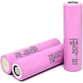
Some types of 18650 have been modified adding either a button top and/or internal protection circuit. This can increase the physical length of an “18650” battery from 65mm to 70mm or in certain cases even longer.
The 18650 cell is our choice when the customer requires that a discharged battery be easily replaced in the field. Having extra batteries and an external charger would allow their product to operate continuously.

Lithium-ion Polymer Battery
Lithium-ion polymer batteries are commonly known as Lithium polymer or LiPo batteries. These rechargeable batteries are evolved from Lithium-Ion batteries. In lithium-Ion batteries, the electrolyte is made of organic solvent, while Lithium polymer batteries are composed of solid polymer electrolyte such as polyethylene oxide or polyacrylonitrile. This electrolyte is a plastic-like film which does not conduct electricity but allows ion exchange. The polymer electrolyte replaced the conventional porous separator, which is immersed in electrolyte.
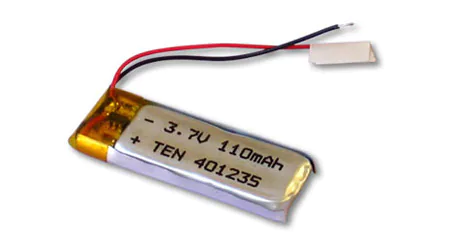
The primary advantage of Lithium Polymer batteries is that they have a flexible structure which allows manufacturers to shape them in different ways. Li-Po batteries are used in radio control equipment, such as radio-controlled aircrafts, radio-controlled cars and large scale model trains. They are also popular choices in portable electronic devices such as cellular phones, tablet computers, gaming console controllers and other wireless hand held electronics


